


GUIDE TO THE CORRECT USE OF THE PRODUCTS
Following the EEC directive no. 83/374 implemented by Italy with DPR no. 224 of 24/05/1988, the user must comply with and apply all the recommendations provided by the manufacturer regarding use, assembly as well
as preventive and periodic maintenance of its products. Such recommendations are summarised in the following paragraphs.
WHEELS AND CASTORS
WHEEL MAXIMUM LOAD AND CARRYING CAPACITY
The carrying capacity declared by the manufacturer is the maximum value, expressed in daN(1daN = 1,019 Kg), that a wheel or a bracket can be subjected to without reducing its operating efficiency. The user must check the suitability of the carrying capacity declared by the manufacturer in relation to the load, the wheel and bracket layout on the trolley to be moved, the number of them actually in contact with the ground and any other conditions (type of surface on which the trolley moves, temperature, humidity, presence of aggressive chemical agents in the operating environment) that may affect the operating conditions of the mechanical moving parts.
LOAD CAPACITY AND WHEEL SELECTION
SOLID LOAD : MINIMUM CARRYING CAPACITY REQUIRED = (LOAD WEIGHT + TROLLEY TARE) : 3
LIQUID LOAD : MINIMUM CARRYING CAPACITY REQUIRED = (LOAD WEIGHT + TROLLEY TARE) : 2
TRACTIVE FORCE
The user must check that the force needed to move the trolley with the foreseen load is compatible with current provisions.
SPEED
The maximum speed for which refers to the rated carrying capacity is 4 km/h (1 .1 m/s). For applications at higher speeds, please contact the manufacturer.
FLOOR
The rated load capacity declared in this catalogue refers to use on smooth and compact floors in good condition. Uneven floors, obstacles and dislevels require wheels with a larger diameter and a covering
with greater elasticity.
TRACTION VEHICLES AND MOVING INTENSITY
The rated carrying capacity declared in this catalogue refers to manual handling with interruptions during use. For continuous operation or motorised handling, please contact the manufacturer.
ENVIRONMENT
The user must check that the materials used to make the choosen product are compatible with physical-chemical conditions of the operating environment (humidity, temperature, aggressive agents etc.).
The catalogue indicates the "normal" operating conditions for each kind of wheel and castors.
ELECTRICAL CONDUCIBILITY
Products that ensure electrical conductivity from the fastener to the tread are available. The electrical resistance of these products is less than 10.000 ohms, measured by ohmmeter or other suitable
device for measuring electrical resistance with an open-circuit voltage of 500 VDC and with internal impedance such that the output voltage does not fall below 50 VDC when the instrument is loaded with an external resistance of 1.000 ohms.
After installation the user is required to check that electrical conductivity from the trolley to the tread is ensured.
BRAKING AND OR LOCKING DEVICES
The manufacturer of wheels and castors for industrial, civil and domestic use, produces castors equipped with brakes and/or locking devices. They are of static type (to be applied when the trolley is stationary), and they are designed to park the trolley on slopes of generally no more than 3%, under the condition that at least two wheels of the trolley equipped with such devices are in contact with the ground. Braking devices are not suitable to withstand impulsive or inertial stresses on the trolley.
INCORRECT ACTIONS
To use wheels and brackets correctly, absolutely avoid the following:
· overloads;
· non-uniform load distribution;
· the violent application of the load;
· extended stationary periods under load;
· impacts and collisions;
· falling from different heights;
· activation of locks and/or brakes while the trolley is moving ;
· moving the trolley with locks and/or brakes engaged ;
· parking the trolley with the locks and/or brakes engaged on slopes of more than 3%;
· washing with chemically aggressive cleaners ;
· replacing the wheel and/or bracket with spare parts that do not comply with the manufacturer specifications.
STORAGE
Products must be stored in a well-ventilated area, without excessive humidity, with a thermal excursion ranging between -10 and + 40 °C and protected from dust. Never expose products to direct sunlight for extended periods of time and, in general, avoid extended storage.
INSTALLATION
For effcient production operation and extended service life, follow the assembly instructions listed below :
The assembly of wheel-bracket assemblies must be performed in full compliance with the assembly cycle that the manufacturer has defined for the specific application. Customer-performed assemblies exempt the manufacturer
from responsability for product damage or defects directly attributable to assembly not in accordance with the manufacturer's specifications.
WHEEL-BRACKET MOUNTING
- check the mechanical strength of the attachment parts (axle sets, nuts, washers) used for the type of assembling (projecting or fork) and the load to which they are subjected;
- House the axle set horizontally on the wheel, perpendicular to the operating direction, and prevent it from rotating;
- check that the nut is tightened on the axle set;
- check that the wheel rotates freely once the installation has been completed;
BRACKET MOUNTING ON THE TROLLEY
The trolley structure must be sized to withstand the stresses to which it is subjected and ensure the coplanarity of the attachment surfaces.They must be flat, horizontal and sized to guarantee that the corresponding bracket attachment surfaces are perfectly coplanar in the attachment point;
Connecting through welding is absolutely not recommended;
It is recommended:
· to mount the top plate bracket using screws, nuts and washers with the sizes and quantity indicated by the manufacturer;
· to tighten the nuts or screws with the appropriate torque;
· to guarantee that the axle set, for fixed castors, is perpendicular to the operating direction;
· to guarantee that brackets with a solid stem are attached to tubular structures with precise tolerances;
· to attach the stems with the cross hole with screws that have an adequate diameter and length;
· to guarantee that the tubular structure of the trolley rests completely on the bracket attachment surface;
· to guarantee, for brackets with a threaded stem or bolt hole, that the bracket connection surface adheres completely;
· the bolt hole brackets must be attached using screws with the diameter indicated by the manufacturer.
MAINTENANCE
The user must carry out scheduled maintenance involving the inspections listed below at a frequency
TROLLEY STRUCTURE CHECK AND MAINTENANCE
Check for any damage to the trolley frame that may have compromised the proper connection of the wheel-bracket assemblies. Check that the castor screw securings are correctly tightened to the trolley structure.
WHEELS AND BRACKETS INSPECTION AND MAINTENANCE
Check that the wheel-bracket assemblies are intact, fully operational and without excessive backlash, wear, deformation.
· check the effectiveness of any locking and/or braking devices, if present;
· verify that environmental conditions have not altered the product (oxidation, corrosion, foreign bodies, etc.),reducing its operating efficiency;
· for products that ensure electrical conductivity, clean the rolling strip and periodically check the electrical conductivity;
· verify the proper tightening of the wheel axle on the bracket by resetting the correct torque;
· Lubricate moving parts with lubricants suitable for the specific application.
The following diagram shows the maximum time interval that can elapse between two follow-up checks. For particularly heavy-duty uses, the time between follw-up checks should be evaluated in relation to the specific application.
| Check and maintenance required | Periodic check | |
|---|---|---|
| Trolley Structure / Frame | Damage to the trolley's frame | 12 Months |
| Trolley Structure / Frame | Tightening of connection parts | 6 Months |
| Wheels and Brackets | Product integrity | 6 Months |
| Wheels and Brackets | Braking device effectiveness | 3 Months |
| Wheels and Brackets | Product alteration | 6 Months |
| Wheels and Brackets | Electrical conductivity | 3 Months |
| Wheels and Brackets | Wheel axle tightening | 6 Months |
| Wheels and Brackets | Lubrication | 6 Months |
Please note : after each washing of the units restore lubrication.
DISPOSAL AND RECOVERY METHODS FOR PRODUCTS
To proceed with the disposal and/or recovery of products at the end of their life cycle, first disassemble the wheel-bracket units from the equipment on which they are installed. Then, disassemble the units themselves into their component parts, which are:
- bracket
- axle unit(screw, bushging, spacers, nut)
- wheel
Particularly, the separation of the wheel from the bracket is crucial if the wheel is mainly made of plastic material or aluminum alloy.
Below is some information regarding the disposal and recyclability of the main materials that make up wheels and brackets for industrial handling.
It is recommended, in any case, to compare and supplement these guidelines with the procedures and regulations established by the waste disposal authority in the location where the products are used.
Brackets and axle components
Iron and stainless steel can be recycled as ferrous scrap.
Wheels
It's recommended to provide a preliminary treatment to separate the different materials in the wheels, in order to ensure their proper disposal and/or recovery.
- Steel and cast iron can be recycled as ferrous scrap
- Aluminum alloy can be recycled as non-ferrous metal
- Plastic, thermoplastic rubber and vulcanized rubber components can be recycled once separated from ferrous and nonferrous metals
- Thermosetting resins can be disposed of in landfill.
- Polyurethanes can be disposed of in landfills once separated from ferrous and nonferrous metals.
- Shrink film packaging is recyclable as low-density polyethylene (PE-LD). Wooden pallets can be reused or recycled. Any paper or cardboard packaging can be returned to the paper supply chain.
USER INFORMATION AND OBLIGATION OF INSTRUCTION
In compliance with the user information and obligation of instruction, as required by the European directive, the manufacturer provides the user with catalogs, technical publications and manuals, according to the specifications required.
LOAD CAPACITIY CALCULATION
Critical to wheel selection is the calculation of the required load capacity, determined by the following formula :
Q = Pu + Pc / n
Q = requested load capacity of the wheel; Pu = weight to be carried;; Pc = trolley tare; n = 3 for a 4-wheeled trolley with solid load, n = 2 for a 4-wheeled trolley with liquid load
Manual handling
In case of manual handling with a single operator (trolley speed < 4 km/h), the wheel should be chosen by comparing the rolling resistance provided by the manufacturer with that resulting from the following formula:
S = Pu + Pc / n
dove: S = resulting rolling resistance; Pu = weight to be carried; Pc = trolley tare; n = number of trolley wheels (max 4)
Mechanical handling using traction vehicles
In case of mechanical towed handling, the choice of wheel is influenced by the operating speed. Dynamic wheel load capacity normally refers to a speed ≤ 4 Km/h (1,1 m/s).For higher values you need to use a correction factor (contact the manufacturer).
Self-powered mechanical handling
In self-powered trolleys the wheels are subjected to special stresses. Since there are so many factors to be evaluated, it's recommended to contact directly the manufacturer.
AXLES
The load capacities given in the tables represent the maximum permissible load at a speed of 40 km/h for trailers in multi-axle configuration, and always refer to single pneumatic wheels with center flange rims.
For use in single-axle, close-axle, shifted-flange wheel or twin-wheel configuration, consult the manufacturer.
The user, after identifying the product corresponding to the application and the maximum operating speed, must verify that the cross-section of the selected axle is suitable for the distance between the wheels centerline and the attachment point of the axle to the trailer frame: for this purpose you can use the following graph
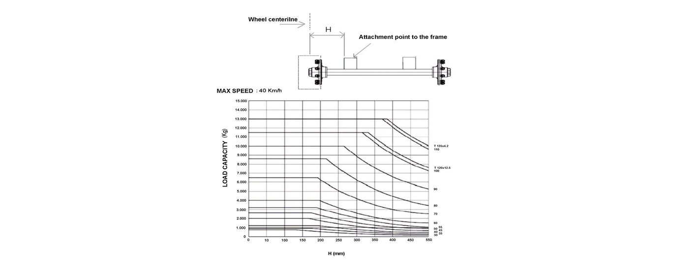
The tables and charts in this catalog are valid for tires with a maximum static radius of 600 mm. For higher values and for tires with low pressure inflation, consult the manufacturer. Brake performance meets the requirements set by current European standards.
SUITABILITY
The suitability of slewing rings must be confirmed for each specific case by the manufacturer.
The use of slewing rings type Y,K,X,T and R is limited by the following table

The data in the table refer to intermittent rotations and horizontal working position.
In all other cases consult the manufacturer.
LOAD CAPACITY
The load capacities given in the catalog indicate the maximum applicable axial load in the absence of overturning moment, uniformly distributed over the slewing ring.
Slewing rings type Y,K,X,T and R are suitable in applications with overturning moment. In these cases consult the manufacturer for determination of equivalent loads and verification of the suitability of the slwing ring with load diagrams.
SPEED
In vehicle applications, slewing rings transmit not only axial load but also radial load and moment.
Type W slewing rings with H = 55 and H = 65 can be used on light vehicles with speeds up to 25 km/h, other types up to 40 km/h.
Type J slewing rings can be used on vehicles with speeds up to 110 km / h.
The nominal load capacity declared by the manufacturer refers to use on smooth, compact surfaces in good maintenance condition. For use on uneven surfaces, obstacles, inclines, and for higher speeds, please consult the manufacturer.
INSTALLATION
Slewing rings type W, Z and J
The installation must be carried out on a flat and rigid surface. The slewing ring must rest on the connecting structure for at least 50% of its surface area. The support areas must be symmetrically distributed
relative to the direction of movement.
It is advisable for the position of the ball introduction plug (recognizable by the weld on the outer ring track)to be located between 45° and 90° relative to the direction of movement.
Use bolts of at least class 8.8 for fastening. Consult the manufacturer for bolt sizes and correct tightening torques.
The insertion of appropriate brackets (at least 4 on each side) welded to the support structure allows the bolts to be unloaded from the radial forces due to accelerations and decelerations.
Perform a complete greasing of the slewing ring before installation. Welding the slewing ring to the support structure and drilling holes at the location of the ball insertion plug are not permitted.
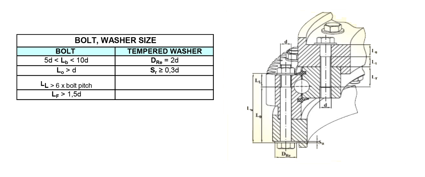
Slewing rings type Y,K,X,T and R
The connecting structure must ensure rigidity against torsion and bending, and compatibility with the fastening bolts (recommended to be steel with a tensile strength of at least 500 N/mm²).
After installation, check that the deflections under maximum load do not exceed the values given in the following table:

The flatness of the support surface must be ensured within the tolerances specified in the following table(for flatness correction use synthetic resins):

Slewing rings type Y,K,X,T e R
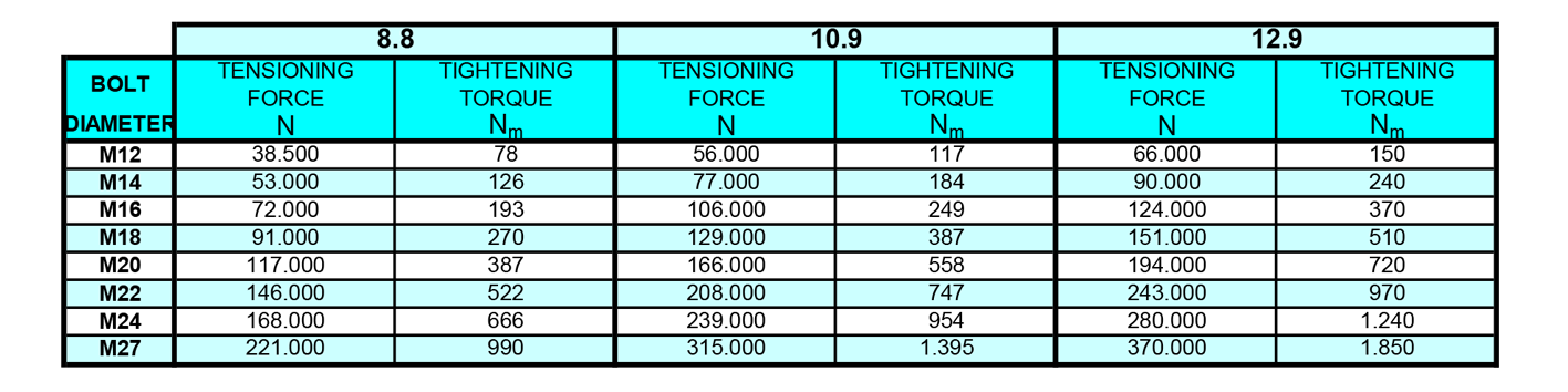
For fastening, use bolts of class 8.8, 10.9, and 12.9 with sizes indicated in the following table :
Bolts must be tensioned with a torque wrench according to the tightening torques given in the following table
MAINTENANCE
It's needed to perform periodic checks of lubrication, bolt tensioning, gasket conditions and machine clearances.
Perform lubrication after the first 50 hours of service and following every 100 hours.
Use preferably lithium lubricants corresponding to DIN 51825 K2K - 20 and ISO L-X -BCHA2 standards (e.g. ESSO BeaconEP2, MOBIL Mobilux EP2, AGIP GRMU/EP2, SHELL Calithia EP2).
Bolt tensioning must be checked every 100 service hours.
TRANSPORT AND STORAGE
Transport the slewing rings in a horizontal position avoiding bumps and shocks especially in the radial direction.
The packaged slewing rings, protected with anti-corrosion oil, can be stored away from the elements for a period of about 6 months. Use chloride-free thinners to remove the protective oil.
DISPOSAL METHODS
Slewing rings are made of normalized C45 steel, so they can be disposed of as ferrous scrap.